 MakerKit株式会社
産業用 車輪脚ロボットIndustrial wheel-legged robot產業用輪足機器人
機構・アクチュエータ選定・トルク設計から、強化学習、実機への移植、キャリブレーションまで。すべての判断を実測とシミュレーションの数字で詰めています。From mechanics, actuator selection and torque budgeting to reinforcement learning, transfer to hardware and calibration. Every decision is pinned down with measured and simulated numbers.從機構、致動器選型與扭矩設計,到強化學習、移植實機與校準。每個判斷都以實測與模擬數字把關。
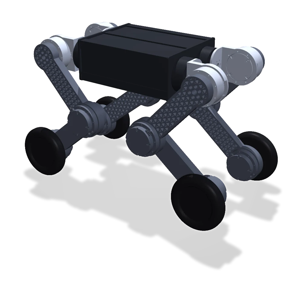
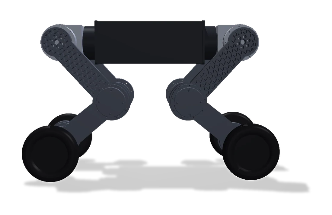
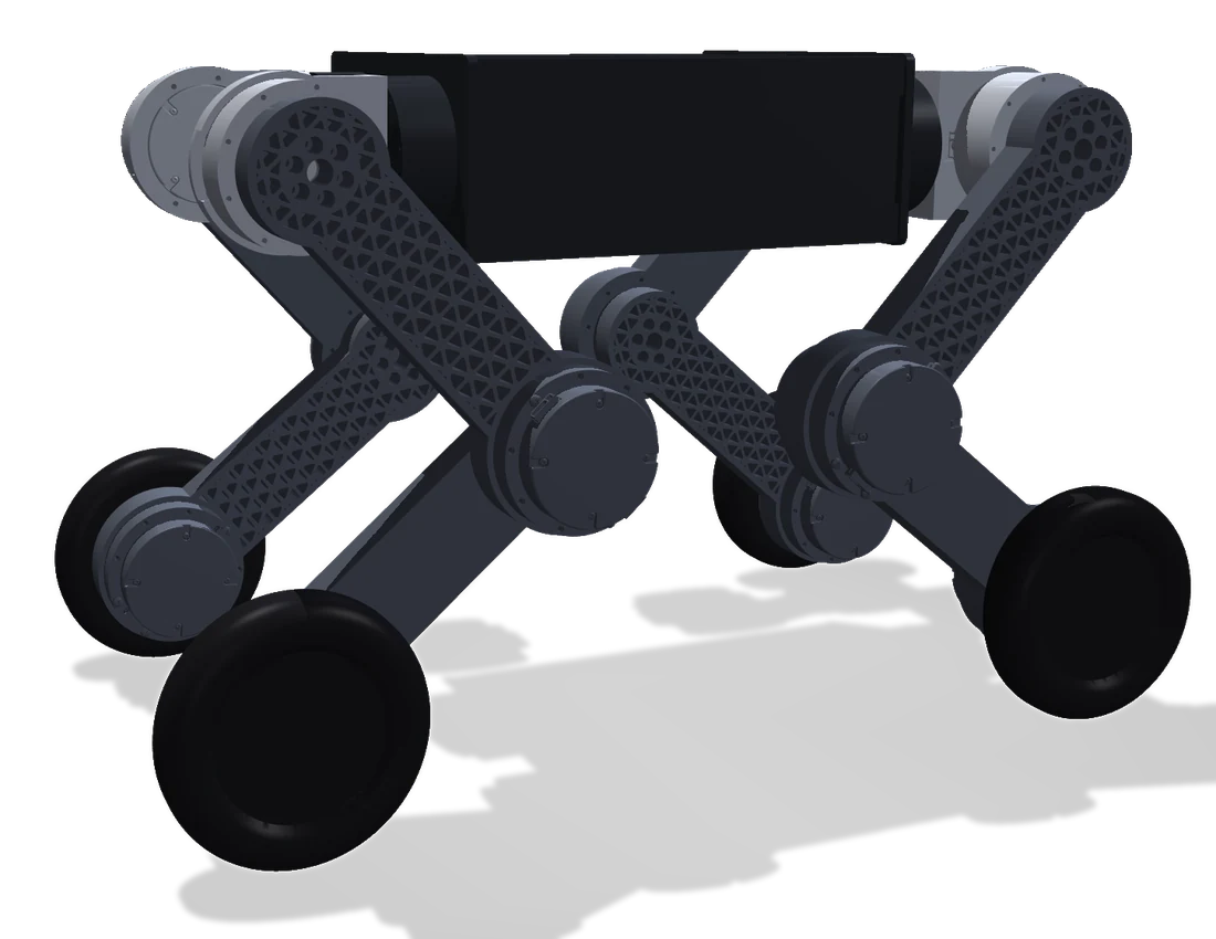
基本構成Configuration基本構成
| 関節 | 16 軸(4 脚 × 股関節の開閉・股関節・膝・車輪) |
|---|---|
| アクチュエータ | 一体型関節アクチュエータ(準ダイレクトドライブ) |
| 移動 | 歩行と車輪走行を切り替え |
| 制御 | 学習済みポリシー 50 Hz + 関節 PD 制御 |
| 校正 | 実機キャリブレーション受入精度 1.28° |
| Sim-to-Real | 同一ポリシーの足上げ高さ:シミュレーション 49.9–51.5 mm / 実機 51.7–55.8 mm(差 2–4 mm) |
| Joints | 16 (4 legs × hip abduction, hip, knee, wheel) |
|---|---|
| Actuators | Integrated quasi-direct-drive joint actuators |
| Locomotion | Switches between walking and rolling |
| Control | Learned policy at 50 Hz + joint-level PD |
| Calibration | On-robot calibration accepted at 1.28° |
| Sim-to-real | Foot-lift height of the same policy: 49.9–51.5 mm in simulation vs 51.7–55.8 mm on the robot (2–4 mm gap) |
| 關節 | 16 軸(4 腿 × 髖外展、髖、膝、輪) |
|---|---|
| 致動器 | 一體化關節致動器(準直驅) |
| 移動 | 行走與輪式滾動切換 |
| 控制 | 已訓練策略 50 Hz + 關節 PD 控制 |
| 校準 | 實機校準驗收精度 1.28° |
| Sim-to-Real | 同一策略的抬腳高度:模擬 49.9–51.5 mm / 實機 51.7–55.8 mm(差 2–4 mm) |
トルク設計 — 需要 ≤ 供給Torque budget — demand ≤ supply扭矩設計 — 需求 ≤ 供給
関節トルクの需要は「足先の力 × モーメントアーム」で決まります。脚の姿勢ごとにヤコビアン J から τ = Jᵀ F を計算し、アクチュエータが供給できるトルク(連続定格・定格・ピーク)と照合します。連続定格は実際の放熱条件で下げて見積もります。
Joint torque demand is set by foot force × moment arm. For every leg posture we compute τ = Jᵀ F from the Jacobian J and check it against what the actuator can supply (continuous, rated and peak torque), with the continuous rating derated for the actual cooling.
關節扭矩需求由「足端力 × 力臂」決定。對每個腿部姿態由雅可比矩陣 J 計算 τ = Jᵀ F,再與致動器能供給的扭矩(連續、額定、峰值)比對;連續額定依實際散熱條件降額估算。
| 動作 | 関節トルク最大値 | 判定 |
|---|---|---|
| 四脚立位 | 0.84 N·m | 連続定格内 |
| 三脚支持(内力ゼロの力配分 + Jᵀf) | 5.56 N·m | 定格内・短時間 |
| 三脚支持(単純な PD で押し付け) | 20.2 N·m | ピーク超過 ✕ |
| 踏み換え(柔軟制御 kp ≤ 50・足上げ ≤ 20 mm) | 2.6 N·m | 連続定格付近 |
| 踏み換え(高剛性 kp = 120) | 最大 43 N·m | ピーク超過 ✕ |
| うずくまりからの起立(四脚同時・高剛性) | 約 12 N·m | ピーク内・定格超 |
| Motion | Max joint torque | Verdict |
|---|---|---|
| Standing on four legs | 0.84 N·m | Within continuous |
| Three-leg support (zero internal force + Jᵀf) | 5.56 N·m | Within rated, short |
| Three-leg support (naive PD push) | 20.2 N·m | Exceeds peak ✕ |
| Stepping (compliant, kp ≤ 50, lift ≤ 20 mm) | 2.6 N·m | ≈ continuous |
| Stepping (stiff, kp = 120) | up to 43 N·m | Exceeds peak ✕ |
| Rising from a crouch (all legs, stiff) | ≈ 12 N·m | Within peak, above rated |
| 動作 | 最大關節扭矩 | 判定 |
|---|---|---|
| 四腿站立 | 0.84 N·m | 連續額定內 |
| 三腿支撐(零內力分配 + Jᵀf) | 5.56 N·m | 額定內・短時 |
| 三腿支撐(單純 PD 硬壓) | 20.2 N·m | 超過峰值 ✕ |
| 原地踏步(柔順控制 kp ≤ 50・抬腳 ≤ 20 mm) | 2.6 N·m | 約等於連續額定 |
| 原地踏步(高剛性 kp = 120) | 最高 43 N·m | 超過峰值 ✕ |
| 從蜷縮起身(四腿同時・高剛性) | 約 12 N·m | 峰值內・超額定 |
9.5 kg の実験機に実測摩擦を入れた物理シミュレーション 1,585 条件の結果。供給側:連続 2.5(放熱条件で降格)/定格 6 /ピーク 17 N·m。膝のモーメントアーム(ヤコビアンから)79–141 mm。1,585 physics-simulation runs of a 9.5 kg test machine with measured friction. Supply: continuous 2.5 (derated for cooling) / rated 6 / peak 17 N·m. Knee moment arm from the Jacobian: 79–141 mm.9.5 kg 實驗機、代入實測摩擦的物理模擬 1,585 組結果。供給側:連續 2.5(依散熱降額)/額定 6 /峰值 17 N·m。膝關節力臂(由雅可比)79–141 mm。
- 必要トルクを決めるのは「立つ」ではなく、段差の蹴り上げと着地
- 踏み換えのピークは制御剛性 kp にほぼ比例 — 柔軟に制御すれば 1/4 以下に
- 同じ三脚支持でも、力の配分次第で必要トルクは約 4 倍変わる
- Peak demand comes from stepping up and landing, not from standing
- Stepping peaks scale almost linearly with stiffness kp; compliant control cuts them to under a quarter
- The same three-leg stance needs about 4× less torque with the right force distribution
- 決定扭矩上限的不是「站著」,而是蹬上台階與落地
- 踏步峰值幾乎與控制剛性 kp 成正比;柔順控制可降到四分之一以下
- 同樣的三腿支撐,力分配不同,所需扭矩相差約 4 倍
アクチュエータのシステム同定Actuator system identification致動器系統識別
シミュレーションの仮定値をそのまま使わず、実機のアクチュエータを台上で測って置き換えます。仮定値との差は、摩擦で約 5 倍、粘性減衰で 50 倍以上ありました。
We do not trust assumed simulation parameters: the real actuators are measured on the bench and substituted in. The assumed values were off by about 5× for friction and more than 50× for viscous damping.
不直接沿用模擬的假設值,而是在台架上實測致動器後替換。假設值與實測相差:摩擦約 5 倍、黏滯阻尼 50 倍以上。
| 項目 | 実測値 | 備考 |
|---|---|---|
| クーロン摩擦(動摩擦) | 0.143 N·m | 4 回測定・ばらつき ±5% |
| 静止摩擦 | 0.24 N·m | 動摩擦より大きい |
| 粘性減衰 | ≈ 0 | 摩擦の 1/40 未満 |
| トルク定数 | 0.107 N·m/A | 電流からトルクへの換算 |
| 制御遅延 | 7 ms | シミュレーションに遅延として反映 |
| PD ゲインの実効倍率 | 1.05 | 指令値に対する実効値 |
| Parameter | Measured | Note |
|---|---|---|
| Coulomb (dynamic) friction | 0.143 N·m | 4 runs, ±5% |
| Static friction | 0.24 N·m | Higher than dynamic |
| Viscous damping | ≈ 0 | Below 1/40 of friction |
| Torque constant | 0.107 N·m/A | Current-to-torque |
| Control latency | 7 ms | Modelled as delay in simulation |
| Effective PD gain factor | 1.05 | Effective vs commanded |
| 項目 | 實測值 | 備註 |
|---|---|---|
| 庫侖摩擦(動摩擦) | 0.143 N·m | 量 4 次・離散 ±5% |
| 靜摩擦 | 0.24 N·m | 大於動摩擦 |
| 黏滯阻尼 | ≈ 0 | 不到摩擦的 1/40 |
| 扭矩常數 | 0.107 N·m/A | 電流換算扭矩 |
| 控制延遲 | 7 ms | 在模擬中以延遲建模 |
| PD 增益實效倍率 | 1.05 | 實效值/指令值 |
ゲイン設計と安定性Gains and stability增益設計與穩定性
関節の PD 制御は「ばね(kp)とダンパ(kd)」です。シミュレーションで安定でも、実機では遅延と摩擦のせいで減衰が足りなくなります。実機試験では kp 30 / kd 0.5 で振動が発散して保護停止し、kp 10 / kd 1.5 で安定しました。ゲインは遅延を含めた減衰比で決めています。
Joint PD control is a spring (kp) and a damper (kd). What is stable in simulation can be under-damped on hardware because of latency and friction: on the robot, kp 30 / kd 0.5 oscillated until the protection tripped, while kp 10 / kd 1.5 was stable. We set gains by the damping ratio with latency included.
關節 PD 控制就是「彈簧(kp)與阻尼(kd)」。模擬中穩定,實機可能因延遲與摩擦而阻尼不足:實測 kp 30 / kd 0.5 振盪發散觸發保護,kp 10 / kd 1.5 則穩定。增益以含延遲的阻尼比決定。
シミュレーションから実機へFrom simulation to the real robot從模擬到實機
- 並列物理シミュレーションGPU 上で数千台を同時に学習。地形カリキュラムとドメインランダマイゼーション(質量・摩擦・遅延)。
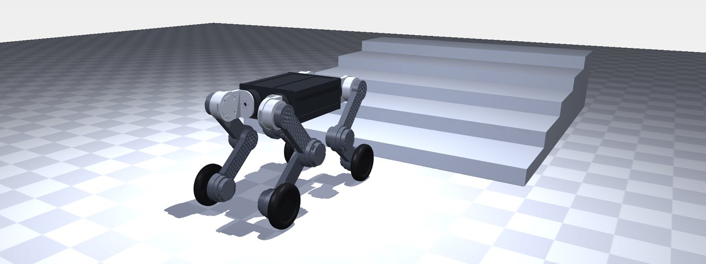
- 能力で受け入れ「倒れなかった率」ではなく「何 cm の段差を登れたか」など能力で判定。
- 別エンジンで交差検証Sim-to-Sim:物理エンジンを替えても同じ性能が出るかを確認。
- 実機パラメータの反映システム同定の結果をシミュレーションに戻して再学習。
- 実機試験・校正安全ゲートの下で段階的に出力を上げて実機へ。
- Parallel physics simulationThousands of robots trained at once on GPU, with terrain curricula and domain randomization (mass, friction, latency).
- Accept on capabilityJudged on capability, such as how high a step it climbs, not on how often it avoided falling.
- Cross-check in a second engineSim-to-sim: the same policy must perform the same in a different physics engine.
- Feed back measured parametersSystem-identification results go back into simulation for retraining.
- Hardware tests and calibrationOutput is raised step by step behind safety gates.
- 並行物理模擬在 GPU 上同時訓練數千台,搭配地形課程與域隨機化(質量、摩擦、延遲)。
- 以能力驗收不看「沒摔倒的比例」,看「能爬上幾公分的台階」等能力。
- 換引擎交叉複核Sim-to-Sim:換一個物理引擎,性能仍須一致。
- 實測參數回饋把系統識別結果放回模擬中重新訓練。
- 實機測試與校準在安全閘門下逐步提高輸出上實機。
安全設計Safety by design安全設計
- トルク上限と持続トルク(ストール)監視による焼損防止 — 温度センサーだけに頼らない
- 姿勢の傾き・センサー値の更新停止を検知して停止
- アクチュエータ側の通信途絶保護に頼らず、ソフトウェアで多重に監視
- 物理的な非常停止
- Burn-out protection by torque limits and sustained-torque (stall) monitoring, not temperature sensors alone
- Stops on excessive tilt or stale sensor data
- Does not rely on actuator-side communication timeouts; monitoring is layered in software
- Physical emergency stop
- 以扭矩上限與持續扭矩(堵轉)監測防燒毀,不只靠溫度感測器
- 偵測姿態過度傾斜或感測值停止更新即停機
- 不依賴致動器端的通訊逾時保護,改由軟體多重監測
- 實體急停開關
納品物Deliverables交付物
- 機構 CAD とシミュレーション用ロボットモデル(URDF ほか)
- 学習済みポリシー(ONNX)と学習設定一式
- アクチュエータ同定データと受入試験レポート
- キャリブレーション・デプロイ用ツール
- Mechanical CAD and simulation robot models (URDF and others)
- Trained policies (ONNX) with full training configuration
- Actuator identification data and acceptance-test report
- Calibration and deployment tools
- 機構 CAD 與模擬用機器人模型(URDF 等)
- 已訓練策略(ONNX)與完整訓練設定
- 致動器識別資料與驗收測試報告
- 校準與部署工具
ロボット開発のご相談はお気軽にPlanning a robot? Let’s talk.有機器人開發需求,歡迎洽詢
構想段階のご相談から、試作・量産設計・納品後の保守まで。日本語・英語・中国語で対応します。From an early idea to prototyping, production design and post-delivery support — in Japanese, English or Chinese.從構想階段的討論,到試作、量產設計與交付後維護;日文、英文、中文皆可。